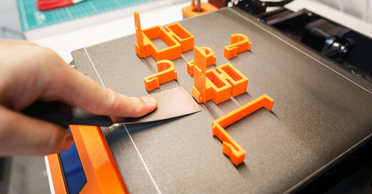
Photo by Jakub Zerdzicki on Pexels
3D Printing Tolerances: What to Expect

3D Printing Tolerances: What to Expect
When businesses first explore 3D printing for their parts, one of the most critical questions is: “How accurate can you get?” Understanding FDM 3D printing tolerances helps set realistic expectations and ensures your designs work the first time. Let’s dive into what’s actually achievable with modern FDM technology and how to design around these constraints.
Standard FDM Tolerance Ranges
Industry-standard FDM tolerances typically fall between +/- 0.2mm and +/- 0.5mm. This range depends heavily on several factors including machine calibration, material properties, and part geometry. For reference, that’s about the thickness of 2-5 sheets of paper - precise enough for many applications, but something to account for in your designs.
Professional-grade FDM printers with proper calibration can achieve tolerances as tight as +/- 0.1mm on smaller features under ideal conditions. However, designing for the tighter end of this spectrum requires understanding which factors affect accuracy most.
What Affects Dimensional Accuracy?
Material Behavior
Different thermoplastics behave differently during and after printing. PLA offers the best dimensional stability with minimal shrinkage (0.2-0.3%), making it ideal when tight tolerances matter most. PETG experiences slightly more shrinkage (0.5-0.8%), while ABS can shrink 0.8-2% as it cools.
Temperature fluctuations during printing can cause warping or dimensional changes. Enclosed printers help maintain consistent temperatures, especially important for materials like ABS that print at higher temperatures (230-250°C).
Part Geometry Matters
Vertical walls (Z-axis) typically achieve better tolerances than horizontal features. This happens because layer height settings directly control Z-axis precision - we can print layers as thin as 0.1mm for fine detail work. Horizontal accuracy depends on nozzle positioning and belt tension, which introduces more variables.
Overhangs and bridges tend to have looser tolerances due to material sagging. Features printed at 45-degree angles often achieve better accuracy than pure horizontal surfaces.
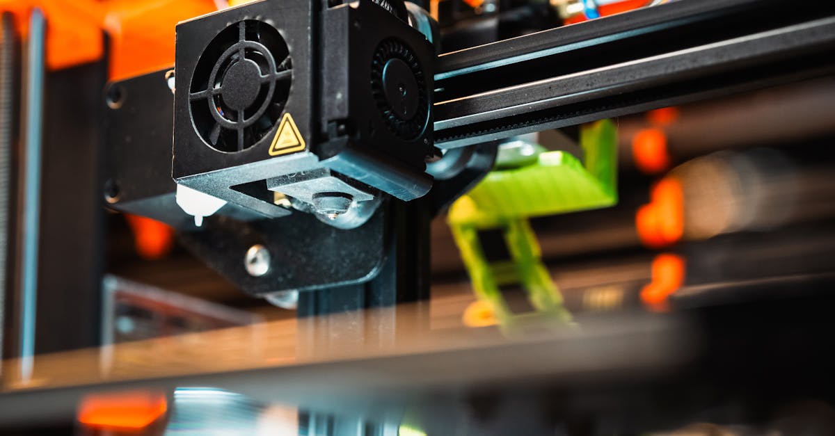
Photo by Jakub Zerdzicki on Pexels
Critical Features That Need Special Attention
Holes and Circular Features
Printed holes typically come out 0.1-0.2mm smaller than designed. This happens because the molten plastic tends to squeeze inward slightly as it cools. When designing press-fit features or bearing seats, compensate by adding 0.1-0.2mm to hole diameters.
For threaded holes, consider these approaches:
- Design holes 0.4mm larger than the tap drill size for metal threads
- Print threads directly only for coarse pitches (M6 and larger work well)
- Use heat-set inserts for the most reliable threaded connections
Mating Parts and Assemblies
When designing parts that fit together, build in appropriate clearances. A minimum gap of 0.2mm works for sliding fits, while 0.15mm allows for tight press fits. For parts that need to rotate freely, aim for 0.4-0.5mm clearance.
Living hinges require special consideration - the hinge line itself should be exactly one layer height thick (typically 0.2mm) for optimal flexibility with materials like PETG or specialized hinge filaments.
How Layer Height Impacts Tolerances
Layer height significantly affects both surface finish and dimensional accuracy. Thinner layers (0.1-0.15mm) provide better resolution for fine details but take longer to print. Standard layer heights of 0.2mm balance quality and speed well for most business applications.
For functional parts where strength matters more than appearance, 0.3mm layers work well and print 33% faster. Just remember that stepped surfaces will be more pronounced with thicker layers.
Design Guidelines for Consistent Results
Wall Thickness Recommendations
Design walls in multiples of your nozzle diameter for best results. With a standard 0.4mm nozzle:
- Minimum wall: 0.8mm (2 perimeters)
- Standard wall: 1.2mm (3 perimeters)
- Strong wall: 2.0mm (5 perimeters)
Odd wall thicknesses like 1.0mm force the slicer to create partial infill passes, which can reduce accuracy.
Feature Size Minimums
The smallest reliable feature size equals 2x the nozzle diameter. For a 0.4mm nozzle, don’t design details smaller than 0.8mm. Text should be at least 1mm wide with 0.5mm depth for clear readability.
Sharp internal corners create stress concentrations and may not print cleanly. Add 0.5-1mm radius fillets to internal corners for better results.
Measuring and Verifying Printed Parts
Professional 3D printing services should verify critical dimensions on your parts. Digital calipers measuring to 0.01mm provide sufficient accuracy for most FDM parts. For tighter tolerance requirements, coordinate measuring machines (CMM) or optical comparators may be necessary.
First article inspection becomes especially important for production runs. Measure the first printed part against your specifications before proceeding with larger quantities. This catches any systematic errors early.
When Standard FDM Tolerances Aren’t Enough
Some applications demand tighter tolerances than FDM can reliably achieve. Options include:
- Post-processing operations like drilling or reaming for precise holes
- Switching to SLA/resin printing for +/- 0.05mm tolerances on small parts
- Hybrid approaches - 3D print the bulk geometry, then machine critical surfaces
Understanding these limitations upfront helps choose the right manufacturing method for each application.
Working with Tolerance Stack-Ups
In assemblies, individual part tolerances compound. If Part A is +0.2mm and Part B is -0.2mm, your worst-case gap could be 0.4mm different than nominal. Design assembly clearances to accommodate worst-case tolerance combinations.
For complex assemblies, consider using common datum surfaces and minimizing the number of mating interfaces. This reduces accumulated error across multiple parts.
Tips for Optimal Results
To achieve the best possible tolerances with FDM printing:
- Orient parts to minimize support material - supports can affect surface accuracy where they attach
- Use consistent print settings - changing speeds or temperatures mid-print affects dimensions
- Allow parts to cool completely before measuring - warm plastic continues to shrink slightly
- Design test features into prototypes to dial in critical fits before production
- Specify which dimensions are critical - this allows focusing efforts where tolerances matter most
Ready to Put This Knowledge to Work?
Understanding 3D printing tolerances helps you design parts that work right the first time. Whether you need rapid prototyping to test fits or small-batch production with consistent dimensions, we’re here to help translate your designs into accurate, functional parts.
Have questions about achieving specific tolerances for your project? Our custom design services team can review your requirements and suggest optimizations for 3D printing success. Start your project today and let’s discuss how to meet your precision needs.
Further Reading
Related Articles

Waterproofing 3D Prints: Methods & Materials
Learn proven techniques to make FDM 3D printed parts waterproof for outdoor and liquid-contact applications.

3D Printing Validation Testing Guide
Master validation testing for 3D printed parts with dimensional checks, strength tests, and material verification methods.

Cost-Per-Part Calculator for 3D Printing
Master the hidden variables that determine your true 3D printing costs and make smarter sourcing decisions.