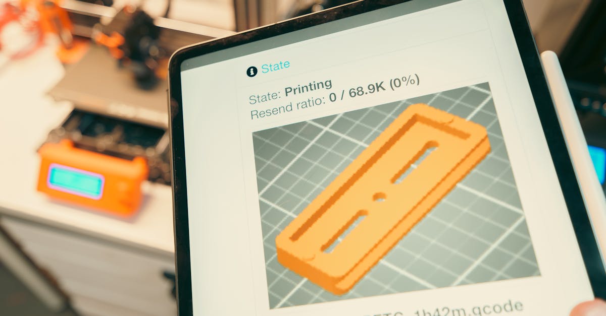
Photo by Jakub Zerdzicki on Pexels
Part Orientation Magic: Print Success Secrets

Part Orientation Magic: Print Success Secrets
Part orientation might seem like a minor detail when submitting files for 3D printing, but it’s actually one of the most critical factors determining print success, part strength, surface quality, and cost. Understanding orientation principles can mean the difference between a $50 prototype and a $150 one - or between a part that performs perfectly and one that fails under load.
Why Does Orientation Matter So Much?
Layer adhesion creates directional properties. FDM 3D printing builds objects layer by layer, creating parts that are strongest along the X-Y plane (parallel to the build plate) and weakest in the Z direction (between layers). Think of it like wood grain - you wouldn’t build a load-bearing beam with the grain running perpendicular to the load.
The orientation of your part affects:
- Mechanical strength and failure modes
- Support material requirements (and therefore cost)
- Print time
- Surface finish quality
- Dimensional accuracy
- Post-processing needs
Understanding Anisotropic Properties
Unlike injection molded or machined parts, 3D printed components have anisotropic properties - meaning their strength varies by direction. Parts can be 10-50% weaker when force is applied perpendicular to layer lines versus parallel to them.
Critical consideration for functional parts. If you’re printing a bracket that will experience pulling forces, orienting it so the layers run parallel to the force vector dramatically improves performance. We see this frequently with drone components and automotive mounting brackets where proper orientation can make or break the application.

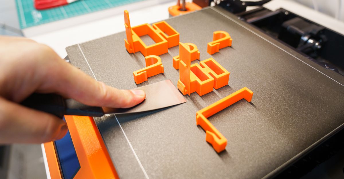
Photo by Jakub Zerdzicki on Pexels
The Support Material Cost Factor
Support material isn’t free - it adds to both material costs and print time. More importantly, surfaces that touch support material require post-processing and never achieve the same quality as surfaces printed directly on the build plate or in free air.
Minimizing Support Requirements
The 45-degree rule saves money. Most FDM printers can successfully print overhangs up to 45 degrees without support. By designing parts with this limitation in mind - or orienting them to take advantage of it - you can eliminate significant support material.
Consider a simple L-bracket. Printed standing up, it requires no support. Printed lying flat, the entire vertical section needs scaffolding. The standing orientation uses less material, prints faster, and produces cleaner surfaces.
When Support Is Unavoidable
Some geometries simply require support regardless of orientation. In these cases, strategic orientation can:
- Place support contact on non-critical surfaces
- Minimize the total volume of support needed
- Enable easier support removal
- Reduce post-processing time
Surface Quality Considerations
Top surfaces print smoothest. The top layer of any 3D printed part typically has the best surface finish, while bottom surfaces (those touching the build plate) show the texture of the print bed. Side surfaces display visible layer lines.
For parts with cosmetic requirements:
- Orient the most visible surface as the top surface
- Consider splitting parts to optimize each section’s orientation
- Use variable layer heights if your service provider offers them
- Plan for post-processing on critical surfaces
Dimensional Accuracy by Axis
FDM printers typically achieve different tolerances on different axes. X-Y accuracy (parallel to the build plate) generally reaches ±0.2mm or better, while Z-axis accuracy might be ±0.4mm due to layer height constraints.
Tight-tolerance features need strategic placement. Holes, slots, and mating surfaces should ideally be oriented in the X-Y plane when possible. A bearing seat printed vertically will be less round than one printed horizontally.
Print Time Optimization
Orientation directly impacts print time, which affects cost. A tall, thin part might print faster lying down despite needing support, while a short, wide part typically prints faster standing up.
Height drives time in FDM printing. Since printers build layer by layer, a part’s height (Z-dimension) is often the primary factor in print duration. A 100mm tall cylinder prints in roughly the same time whether it’s 10mm or 50mm in diameter.
Multi-Part Assembly Strategies
Sometimes splitting is winning. Complex geometries that would require extensive support in any orientation often benefit from being split into multiple components. This approach can:
- Eliminate support entirely
- Improve strength by optimizing each section’s orientation
- Reduce overall print time
- Enable larger parts than the build volume would otherwise allow
We regularly advise customers on part splitting for manufacturing tooling and custom design projects. The small effort of designing snap-fits or alignment features pays off in print quality and cost savings.
Material-Specific Orientation Tips
PLA Orientation Guidelines
PLA’s relatively low strength between layers makes orientation especially critical for load-bearing applications. Parts should be oriented to avoid layer separation under stress. The material’s low temperature resistance means orientation won’t affect heat-related performance much.
PETG Orientation Guidelines
PETG offers better layer adhesion than PLA, making it more forgiving of sub-optimal orientations. However, PETG’s tendency to string means minimizing travel moves through orientation can improve surface quality. Parts requiring chemical resistance benefit from orienting critical surfaces away from layer lines where chemicals might penetrate.
ABS Orientation Guidelines
ABS parts face warping challenges that make orientation crucial. Large, flat surfaces should be minimized on the build plate, and tall, thin features oriented to reduce warping forces. The material’s good layer adhesion makes it suitable for parts loaded perpendicular to layers.
Advanced Orientation Strategies
Variable orientation within one print. Some advanced slicing software allows different orientation strategies within a single part - printing the base with high strength orientation, then shifting to minimize support for overhanging features.
For complex assemblies, consider:
- Printing interlocking parts in their assembled orientation
- Using sacrificial bridges to connect parts during printing
- Orienting for optimal clearance between moving components
- Planning for minimal post-processing of mating surfaces
Common Orientation Mistakes
Ignoring Load Direction
The most expensive mistake is orienting parts without considering how they’ll be stressed in use. A clip or spring printed with layers perpendicular to the flex direction will fail prematurely.
Over-Prioritizing Appearance
While cosmetic quality matters, sacrificing structural integrity for a prettier surface rarely makes sense for functional parts. Post-processing can improve appearance, but can’t fix fundamental strength issues.
Defaulting to Minimal Height
While reducing Z-height often reduces print time, it’s not always optimal. A part might print faster tall and thin than short with extensive support structures.
Working with Your 3D Printing Service
Communication is key. When submitting parts for printing, include notes about:
- Critical dimensions and their required tolerances
- Load directions and stress points
- Surface finish requirements by face
- Any assembly or mating considerations
Professional services like ours evaluate each part individually, but your input on intended use ensures optimal orientation selection. We often suggest orientation changes that can reduce costs by 30-50% while improving part performance.
Ready to Optimize Your Next Project?
Understanding part orientation transforms 3D printing from a prototyping tool to a legitimate manufacturing process. Whether you’re developing rapid prototypes or planning small-batch production, proper orientation ensures success.
Let CLT 3D Printing’s expertise guide your next project. We analyze every part for optimal orientation, balancing strength, quality, and cost to deliver exactly what you need. Our team in Charlotte understands the nuances of FDM printing and helps customers across North Carolina achieve better results through smart orientation strategies.
Ready to put these principles into practice? Start your custom order today and experience the difference professional orientation analysis makes.
Related Resources
Related Articles
Waterproofing 3D Prints: Methods & Materials
Learn proven techniques to make FDM 3D printed parts waterproof for outdoor and liquid-contact applications.

3D Printing Validation Testing Guide
Master validation testing for 3D printed parts with dimensional checks, strength tests, and material verification methods.

Cost-Per-Part Calculator for 3D Printing
Master the hidden variables that determine your true 3D printing costs and make smarter sourcing decisions.