
Photo by Jakub Zerdzicki on Pexels
Designing Snap Fits for FDM 3D Printing

Snap fits are one of the cheapest ways to assemble a product. No screws, no adhesive, no extra hardware, just geometry that clicks together. They are also one of the most common reasons a 3D printed part fails at the first assembly. Good snap-fit design for FDM is not the same as snap-fit design for injection molding, and a latch that works in molded polypropylene can snap off a PLA print the first time someone presses on it.
This guide covers the engineering that makes the difference: strain limits, layer orientation, clearances, and when to give up on a snap fit and use a different fastening method.
Why Do 3D Printed Snap Fits Break?
Layers are the weak direction. FDM parts are built from fused layers, and the bond between layers is weaker than the strength of the extruded filament itself. A cantilever latch printed standing upright puts its highest bending stress right across those layer lines. When the arm flexes, it can delaminate and snap cleanly at the base.
Common materials are not very ductile. PLA is stiff and strong but has low elongation at break, and it can fail with little warning. PETG is noticeably more forgiving and tolerates repeated flexing better. Nylon and TPU are far more flexible, though they are capabilities we offer rather than our daily-driver materials. For a deeper look at how these materials differ, see our PLA vs PETG vs ABS comparison.
Sharp corners concentrate stress. A latch arm that meets the wall at a hard 90-degree corner is a crack waiting to start. Printed parts also have tiny stress risers from layer lines, so geometry that would be borderline in a molded part is often unacceptable in a printed one.
How Do You Calculate Strain in a Cantilever Snap Fit?
The most common snap fit is the cantilever hook, a flexible arm with a lip that deflects as it passes over a mating feature. For a straight arm with constant rectangular cross-section, maximum strain at the root is:
Strain = 1.5 x t x y / L^2
Where t is the arm thickness, y is the deflection needed to clear the lip, and L is the arm length. All dimensions are in the same units.
A worked example. Say your arm is 2 mm thick, 15 mm long, and has to deflect 1 mm to clear the hook. Strain = 1.5 x 2 x 1 / 225, which is about 0.0133, or 1.3 percent. That is a reasonable design target for PETG and on the aggressive side for PLA, particularly if the part will be assembled more than once.
Design targets. As a conservative rule of thumb for FDM, many designers keep peak strain in the range of roughly 1 percent for PLA and somewhat higher for PETG, then validate with printed samples. Exact limits depend on the filament brand, print temperature, and orientation, so treat these as starting points rather than guarantees.
How to lower strain. The formula shows the levers clearly. Lengthen the arm (strain falls with the square of length), reduce its thickness, or reduce the deflection needed. Tapering the arm so it is thinner at the tip than at the root spreads strain more evenly along its length and can cut peak strain substantially.
What Orientation Works Best for Snap Fits?
Keep the flex in the plane of the layers. The strongest approach is to lay the arm flat so the direction of bending is within the XY plane of the print bed. The stress then runs along continuous extruded paths instead of trying to pull layers apart. An arm that stands vertically and flexes sideways is the worst case.
Think about orientation before you finalize the design. If a latch has to flex in a direction that would put it across layer lines, it is often better to rotate the whole part or split the design into two pieces than to rely on a vertical arm. Our part orientation guide goes deeper on how orientation affects strength, surface finish, and support needs.
Make the arm solid. A snap arm should not be infill-dependent. Use enough perimeters (typically 3 to 4 walls on a 0.4 mm nozzle) that the arm is effectively solid, or set a local 100 percent infill region. This is the same principle covered in infill vs walls: walls carry most of the load in thin features.
Photo by Jakub Zerdzicki on Pexels
What Design Details Make the Biggest Difference?
Add a generous fillet at the root. A fillet radius of at least half the arm thickness at the base of the cantilever spreads stress over a larger area. This single change often turns a latch that breaks on the first try into one that survives dozens of cycles.
Use a lead-in angle and a return angle. The lead-in ramp, commonly around 20 to 30 degrees, controls how hard assembly feels. The return face sets whether the joint is permanent or releasable. A steep return face (near 90 degrees) locks tightly and is hard to release. A shallower one, such as 45 degrees, lets the part be opened again.
Keep the engagement small. The hook only needs to catch by a fraction of the arm thickness, often 0.5 to 1.5 mm in typical designs. Bigger hooks mean more deflection and more strain for little extra holding power.
Plan for clearance. FDM prints are not perfect copies of CAD, so mating surfaces need gaps. For snap features that need to slide freely, clearances of roughly 0.2 to 0.4 mm per side are a reasonable starting point depending on the printer and material. Our guides to 3D printing tolerances and tolerance stackup in assemblies explain why these gaps matter and how they add up across multiple parts.
Account for the flexing direction in the housing, too. The wall the hook catches on may also flex, which changes the effective deflection. If both parts are printed in rigid materials, make sure you are not counting on flex that is not really there.
Do Annular Snap Fits and Living Hinges Work in FDM?
Annular snap fits can work for caps and lids. A circular lip that snaps into a groove spreads load around the whole circumference, which suits round enclosures, caps, and covers. Because a printed ring has layers running around it, hoop strength is usually good. The main risk is making the interference too tight, which can crack the ring during assembly. Start with small interference values and test.
Living hinges are a poor fit for rigid FDM materials. Molded polypropylene living hinges survive thousands of flexes. A thin printed PLA or PETG hinge will usually fatigue and crack far sooner, because layer lines and brittle behavior work against it. If you need a flexing hinge, consider a flexible material like TPU (a capability we can discuss for the right project), or switch to a two-part design with a separate pin or a print-in-place pin hinge.
When Should You Skip the Snap Fit?
If it will be opened often. Parts that need frequent access, such as battery doors or service panels, are better served by screws into heat-set inserts. Threaded inserts give repeatable, strong connections that a printed latch cannot match over many cycles.
If it holds constant load. A snap fit that stays deflected, or keeps a spring-like preload, will creep over time. PLA softens at relatively low temperatures (its glass transition is around 55 to 60 C), so a latch in a hot vehicle cabin or near a heat source can relax or deform. PETG and ABS handle warmer conditions better. Our ABS guide and PETG guide cover heat behavior in more detail.
If the product is safety-critical. Do not rely on a printed snap fit as the only retention for anything where failure could cause injury. Add a redundant fastener or validate the design with proper testing.
How Should You Prototype and Validate a Snap Fit?
Print a test coupon first. Before committing to a full enclosure, print small coupons of the latch and the mating feature at two or three clearance values and a couple of arm lengths. This takes little time and material, and it shows you how the specific printer and filament behave.
Test for the real use case. Assemble and disassemble the joint the number of times the product will realistically see. Check it after sitting at temperature, and check the feel of the click, not just whether it holds.
Iterate quickly. This is where rapid prototyping pays off. Changing an arm length or fillet radius costs a few hours of print time, not a new mold. Once the design is proven, small-batch production lets you run dozens or hundreds of units without tooling. For a broader look at how design choices affect cost and success, see our design rules that save money on 3D prints.
Need Help Designing Parts That Snap Together?
If you have an enclosure, housing, or assembly that needs to go together without hardware, we can help refine the design or build it from scratch through our custom design services. We print in PLA and PETG daily and can discuss ABS, ASA, nylon, TPU, and carbon fiber composites when the application calls for them. We serve Charlotte and the surrounding I-77 and I-85 corridor communities and ship nationwide.
Ready to get started? Submit your project through our custom order page with your CAD files or a description of what you need, and we will work with you on a design that holds up in real use.
Related Reading
Related Articles
Creep in 3D Printed Parts: Why Plastic Sags
Creep in 3D printed parts is slow deformation under constant load. Learn which materials resist it and how to design parts that keep their shape.
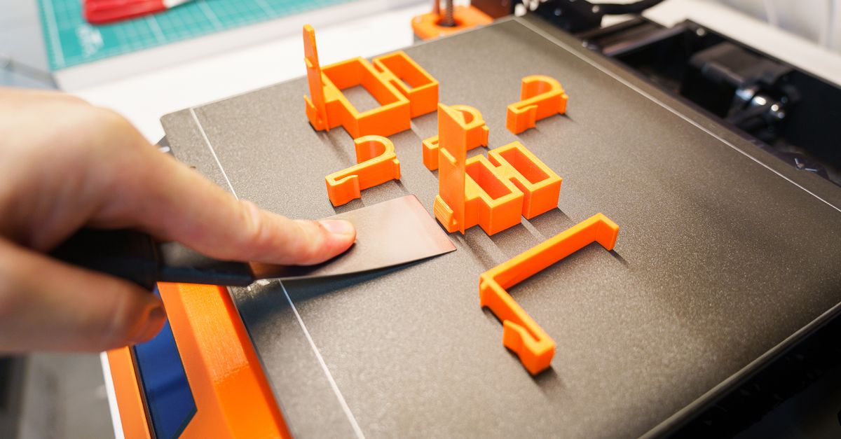
Reverse Engineering Broken Parts for 3D Printing
Reverse engineering parts for 3D printing turns a worn or obsolete component into a usable CAD model. Here is the workflow and the pitfalls to avoid.
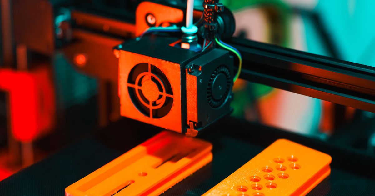
Infill vs Walls: What Makes 3D Prints Strong
3D print strength depends more on walls, orientation, and material than on infill percentage. Here is how to spec parts that hold up without overpaying.