
Photo by Jakub Zerdzicki on Pexels
Splitting Large Parts for FDM Printing

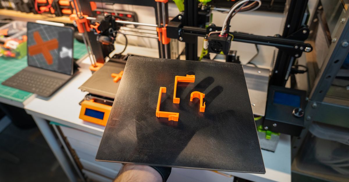
Sooner or later, almost every business that uses 3D printing runs into the same problem: the part they need is bigger than the printer. A dashboard panel, an equipment guard, a display housing, a drone fuselage, a sign, a machine cover. These designs can easily run past 400 mm in one direction, while most FDM machines have build volumes in the range of roughly 220 to 350 mm per side. The good news is that large 3D printed parts are very achievable if you plan the split from the start instead of treating it as an afterthought.
This guide covers where to cut, which joints work in FDM, how to bond the pieces, and how to finish the seams so the final assembly looks and performs like a single part.
Why Split a Part Instead of Printing It Whole?
Build volume is only one reason. Even when a part technically fits, splitting it can be the smarter choice. Large flat footprints are prone to warping, particularly in materials with higher shrinkage like ABS and ASA. A long print also carries more risk: a failure at hour 38 of a 40-hour print wastes far more material and time than a failure on one segment of a multi-piece build.
Splitting lets you orient each piece optimally. A single large part forces one orientation, and that orientation is always a compromise. When you cut the design into sections, each piece can be laid out to put layer lines in the right direction, minimize support material, and put the best surface on the visible face. Our post on part orientation explains why this matters so much for strength and finish.
Smaller pieces are easier to iterate. If one section of a large assembly needs a design change, you reprint that section, not the whole thing. For teams working through rapid prototyping, that can shorten each design cycle considerably.
Where Should You Place the Cut?
Cut location is the single most important decision in a split design. A few rules of thumb hold up well across most FDM work.
Cut perpendicular to the load path when possible, and away from peak stress. A joint will almost always be weaker than the continuous material around it. Avoid placing seams at bolt bosses, hinge points, thin necks, or any area that sees concentrated load. If the part carries a bending load, put the joint near the neutral region rather than at the point of maximum bending.
Hide seams in natural features. Panel lines, steps, corners, and existing edges make excellent split locations because the seam reads as a design element. A seam across a smooth, curved, high-visibility surface is the hardest to disguise.
Keep cuts flat when you can. Flat cut planes print cleanly against the build plate, need minimal support, and mate more accurately. Curved or angled cuts are possible but add complexity to both printing and alignment.
Split to equalize piece size. Two pieces of similar size usually print more predictably than one large piece and one tiny sliver. Very small slivers are fragile and hard to handle during assembly.
Photo by Jakub Zerdzicki on Pexels
Which Joint Designs Work Best in FDM?
A plain butt joint, two flat faces glued together, is the weakest option because the bond area is small and nothing keeps the pieces aligned. Designing in a mechanical joint solves both problems.
Tongue-and-Groove
A continuous ridge on one piece fits into a matching channel on the other. This gives you self-alignment and a much larger bond surface. It works especially well along long straight seams, such as the edges of a large panel.
Dovetail and Keyed Joints
A dovetail locks the pieces together in one direction, which means the joint resists being pulled apart even before adhesive cures. This is useful when assembly needs to hold itself in place while the glue sets.
Pin-and-Socket Alignment
Round pins on one face and matching holes on the other are quick to design and print reliably. Use at least two pins per joint to prevent rotation, and place them asymmetrically so the pieces can only assemble one way. Metal dowel pins (steel or brass) in printed holes add stiffness for parts under more load.
Lap and Scarf Joints
Overlapping the pieces increases bond area dramatically. A lap with 10 to 15 mm of overlap gives an adhesive far more surface to work with than a flat butt joint. Scarf joints, where the cut runs at a shallow angle, spread stress across a longer bond line and can look cleaner on thin-walled parts.
Mechanical Fasteners
For parts that must be disassembled, or that carry real loads, use bolted flanges with heat-set inserts rather than relying on adhesive alone. A printed flange with a row of inserts creates a repeatable, serviceable joint.
Clearance matters. Mating features need gaps built into the design. As a starting point for FDM, plan for roughly 0.2 to 0.3 mm of clearance per side on slip-fit tongue-and-groove or pin features, and test it, because the right number depends on material, nozzle size, and printer. Our guides on tolerances and tolerance stackup go deeper on this, and they are especially relevant when several joints stack up across a large assembly.
How Do You Bond Printed Sections Together?
The right adhesive depends on the material.
PLA. Cyanoacrylate (CA) glue, especially gel formulas, bonds quickly and works well for light-duty joints. For structural joints, a two-part epoxy gives better gap-filling and strength. Keep in mind that PLA softens at relatively low temperatures (around 55 to 60 C), so a bonded PLA assembly left in a hot vehicle or near a heat source can deform at the seam.
PETG. PETG resists many solvents, which also makes it hard to solvent-weld. Two-part epoxy or a plastic-rated structural adhesive is the safest bet, and lightly scuffing the mating surfaces improves adhesion. Test your adhesive on scrap prints first.
ABS and ASA. These materials can be solvent-welded with acetone, which partially dissolves the surfaces so they fuse into one piece. Done well, the resulting joint can be very strong. Done carelessly, it can leave visible melting and warping. If you want to compare material properties before choosing, see our PLA vs PETG vs ABS comparison and the ABS material guide.
General bonding practice:
- Dry-fit every joint before applying adhesive.
- Clean surfaces of dust and oils, and scuff glossy faces lightly.
- Clamp or tape the assembly while the adhesive cures, and check alignment against a flat reference surface.
- Allow full cure time before sanding or loading the part.
How Do You Make the Seams Disappear?
If appearance matters, the seam needs finishing. The standard workflow is to fill the joint line with a body filler or putty, sand progressively through finer grits, apply filler primer, sand again, and then paint. This is the same approach covered in our posts on post-processing and finishing standards. For large visible parts, such as automotive interior panels or display pieces, building the finishing steps into the plan early saves effort later. It is also a common need in classic car restoration work, where large trim and panel pieces often exceed the build plate.
One design tip that helps: add a shallow V-groove or small reveal along the seam on purpose. A deliberate shadow line looks intentional and hides small alignment differences far better than trying to make a perfectly flush joint.
Design Checklist for Large Printed Assemblies
Before you finalize a split design, run through these points:
- Check build volume first. Confirm the maximum size of each piece against the printer you plan to use.
- Place cuts away from stress concentrations and hide them in natural features.
- Add alignment features such as tongue-and-groove, dovetails, or asymmetric pins.
- Maximize bond area with lap joints or interlocking geometry.
- Include clearance in mating features and plan to test-fit a prototype.
- Choose material and adhesive together, not separately.
- Plan the finishing process if the seam will be visible.
- Consider wall thickness and infill near joints, since bond strength depends on solid material at the interface. Our post on infill vs walls explains how to reinforce those zones.
Many of these decisions overlap with general design rules that save money on 3D prints, so it pays to apply them as a set.
Need Help Designing or Printing a Large Part?
If you have a part that is too big for a single print, we can help you figure out the split strategy, joint design, material, and finishing approach before any plastic is printed. Our custom design services can take an oversized concept and turn it into a printable, assemblable set of parts, and we can produce repeat sets through small-batch production once the design is proven. We print primarily in PLA and PETG, and we can discuss ABS, ASA, and other materials when your application calls for them.
Ready to get started? Submit your project through our custom order page and we will review your files and recommend the best approach.
Related Reading
Related Articles
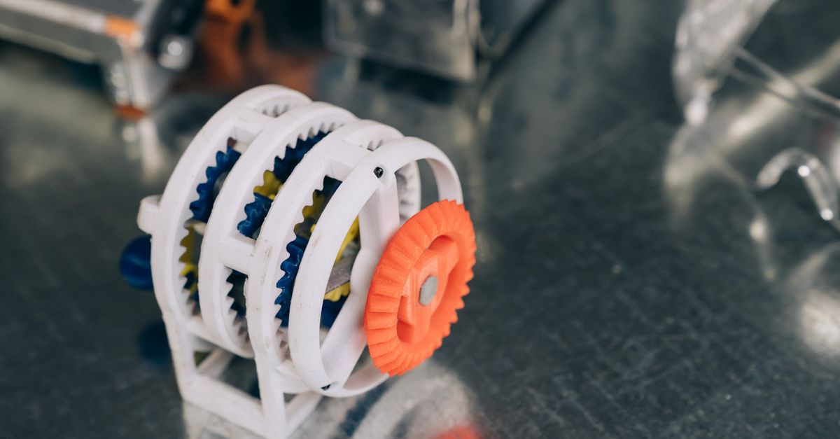
3D Printed Gears and Wear Parts That Last
3D printed gears can work well in the right applications. Learn which materials, tooth designs, and print settings help FDM gears and wear parts hold up.
What Automaker 3D Printing Means for Small Shops
Automaker 3D printing is cutting tooling cost and lead time. Here is what small and mid-size Charlotte manufacturers can borrow from that playbook.
What Drives 3D Printing Lead Times
3D printing lead times depend on more than print time. Learn what drives your schedule and how to shorten it on your next prototype or production run.