
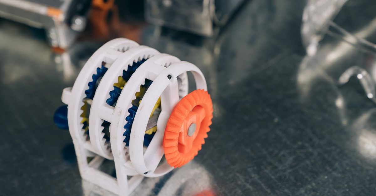
Photo by Mikhail Nilov on Pexels
3D Printed Gears and Wear Parts That Last

Gears are one of the first parts engineers ask about when they discover FDM printing, and one of the first that get printed badly. A gear that looks perfect on screen can chew itself apart in a week if the material, tooth geometry, or print orientation is wrong. Done correctly, though, 3D printed gears are a practical way to replace discontinued parts, build custom mechanisms, and prototype drivetrains without waiting weeks for tooling.
This guide covers what makes plastic gears and wear parts survive in service, and where FDM is the wrong tool for the job.
Where Do 3D Printed Gears Make Sense?
Low-to-moderate torque and light duty cycles. FDM gears are well suited to indicator mechanisms, camera and sensor positioners, small actuators, hand-cranked equipment, dispensers, and display or animation hardware. These applications rarely see shock loads or continuous high-speed operation.
Replacement parts with no available source. Plenty of equipment is still running long after the manufacturer stopped supplying a plastic gear. If you can measure the original, or reverse engineer it from a worn sample, printing a replacement can put a machine back in service. Our post on reverse engineering broken parts covers that workflow.
Prototypes and one-offs. When you are still proving out a gear ratio or housing layout, printing a few variations is far cheaper than ordering machined or molded gears. This is a natural fit for rapid prototyping, where you iterate until the mechanism works and then decide whether to stay in plastic or move to another process.
Custom ratios and unusual geometry. Printing makes it easy to build compound gear trains, integrated shafts, and odd tooth counts that would be expensive to source off the shelf.
Which Material Works Best for Gears and Wear Parts?
Material choice has more effect on gear life than almost any other variable.
PLA. It is stiff and prints crisply, which makes it excellent for prototypes and display mechanisms. For working gears, it is a poor choice under load because it is brittle, wears quickly under sliding contact, and softens at roughly 55 to 60 C. It also creeps under sustained load, which we explain in our creep in 3D printed parts article. Use PLA to test fit and tooth mesh, not for long-term service.
PETG. This is the material we would reach for first on most functional gears we print. It has better toughness and impact tolerance than PLA, handles moderate temperatures better, and resists tooth chipping. It is a bit softer, so tooth profiles can deform slightly under heavy load, but for light and medium duty it is a solid balance of cost and durability. See our PETG guide for more on its properties.
ABS. It offers good toughness and higher heat resistance, which helps when gears sit near motors or in warm enclosures. It requires careful temperature control to avoid warping, particularly on larger gears. Our ABS material guide covers those details.
Nylon. Nylon is the classic plastic gear material in injection molded and machined parts because of its low friction and excellent wear resistance. We can print in nylon, but it is not one of our daily-driver materials, and it demands dry filament and tuned print settings. If your application truly needs wear resistance above what PETG can deliver, read our nylon printing guide and talk to us about feasibility before committing.
TPU. Flexible gears and drive belts or couplers are possible in TPU, but it is an unusual solution. It is best for damping and quiet operation rather than precise power transmission.
What Design Details Matter Most?
Use a larger module than you think you need. The module is the tooth size, and a coarse tooth is much more forgiving in FDM. With a 0.4 mm nozzle, a module of 1.5 or above gives teeth several extrusion widths thick. At module 1.0, the tooth is only about 1.57 mm thick at the pitch circle, which leaves very little room for clean walls. Finer teeth can be printed, but their accuracy and strength drop quickly.
Account for backlash. Printed parts do not match CAD dimensions perfectly. Plan for roughly 0.1 to 0.3 mm of backlash depending on gear size and print quality, and verify with test prints. Too little backlash binds the mesh and generates heat. Too much causes noise, shock loading, and positional slop. Our tolerance guide explains the realistic accuracy to expect from FDM.
Keep tooth counts reasonable. For a standard 20 degree pressure angle, pinions with fewer than about 17 teeth suffer from undercut unless the profile is corrected. Use profile shift or choose a larger pinion if you need a high reduction.
Add fillets and avoid sharp transitions. Stress concentrates at the root of each tooth and at the junction between hub and web. Generous fillets help.
Consider helical or herringbone teeth for smoothness. Helical gears run quieter and share load across more teeth, but they generate axial thrust that the housing must handle. Herringbone gears cancel the thrust and print well on FDM since the geometry has no overhangs when oriented flat.
Design the hub for a real connection. A printed bore with a set screw will often strip. Better options include a D-shaft or keyed bore, a pressed-in metal hub, or a captured nut with a set screw. Heat-set inserts are also useful for clamping hardware.
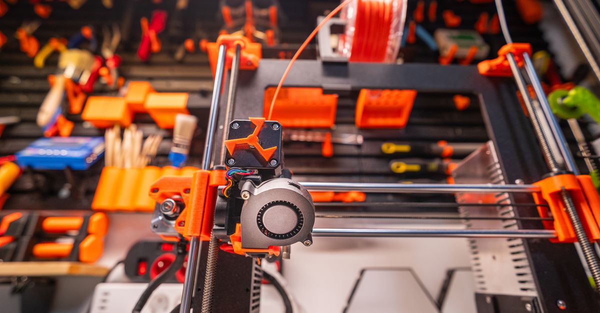
Photo by Jakub Zerdzicki on Pexels
How Should You Orient and Print a Gear?
Print gears flat. With the gear axis vertical, the layers sit in the same plane as the tooth profile. Tooth bending loads then run along the layers rather than across them, where FDM parts are weakest. Printing a gear on its side puts layer lines across each tooth, which invites delamination and tooth shear. This is a specific case of the principles in our part orientation guide.
Prioritize walls over infill. Teeth are thin features made almost entirely of perimeters. Use at least 4 walls, and consider increasing infill to 50 percent or more in the hub and web. Our infill vs walls article goes deeper on why walls drive strength.
Use finer layer heights. A layer height of 0.12 to 0.16 mm gives more accurate tooth flanks than 0.28 mm. Slowing the outer wall speed also improves dimensional consistency.
Mind the first layer. Elephant foot, where the first layer squishes outward, can distort tooth profiles at the base of the gear. A small chamfer on the bottom edge or a tuned first layer compensates.
Hide the seam. Seams create small bumps. Placing them in the root between teeth, or on a face that does not mesh, helps keep the contact surfaces clean.
What About Bushings, Bearings, and Sliding Parts?
Gears are only part of the wear story. Many mechanisms depend on plastic parts rubbing against shafts, rails, or each other.
Use real bearings where speed or load is meaningful. A standard 608 or similar ball bearing pressed into a printed pocket will outlast any printed sliding surface. Design the pocket slightly undersized and test with printed samples, since fit varies by printer and material.
Ream printed bores. Holes print slightly undersized and slightly out of round. For a running fit on a steel shaft, print the hole undersized and ream it to final size. This gives a cleaner surface than relying on the printed dimension.
Pair dissimilar materials. Two identical plastics rubbing together tend to wear faster and sometimes stick. A printed plastic part running on a steel or stainless shaft is usually better than plastic on plastic.
Plan for replaceable wear surfaces. A printed bushing that can be swapped in minutes is more valuable than a high-performance part that requires disassembling the whole machine. This is one of the biggest advantages of printing: a replacement is a file away. Our preventive maintenance guide covers inspection intervals and replacement planning.
Does Lubrication Help?
Often, yes. A thin film of PTFE-based or silicone-based grease can cut friction and heat. Check compatibility, because some petroleum greases and solvents can attack certain plastics and cause cracking over time. Our chemical resistance guide is a good reference before you pick a lubricant. Apply lubricant sparingly, since excess grease collects dust and debris that accelerates wear.
When Should You Choose Something Other Than FDM?
Be honest about the limits. FDM gears are usually the wrong choice when:
- The application involves high torque, shock loads, or safety-critical motion
- The gear runs continuously at high speed, generating frictional heat
- Tight transmission accuracy is required, such as precision indexing
- The part will be exposed to sustained heat near or above the material’s limit
- You need thousands of identical gears at the lowest unit cost
In those situations, machined metal, sintered, or injection molded gears are better. FDM still plays a role as a prototyping tool, letting you validate the design before committing to tooling. Our comparison of 3D printing vs CNC machining can help you decide where the crossover sits for your part.
Printing is also useful for the fixtures and holders around a mechanism. If you are building a test rig to run gears in, our manufacturing tooling and fixtures service can support that.
Get Your Gear Design Right Before You Print
A reliable printed gear comes from matching the load to the material, using a coarse enough tooth, orienting the part for strength, and validating with real testing. If you do not have CAD for the mechanism, our custom design services can model the gear train for you, and we can produce small production runs once the design is proven.
Ready to Print Gears or Wear Parts?
Send us your drawings, a worn sample, or just a description of what the mechanism needs to do. We will review the application, recommend a material, and tell you honestly whether FDM is the right process for it.
Start your custom order and we will take it from there.
Related Reading
Related Articles
What Automaker 3D Printing Means for Small Shops
Automaker 3D printing is cutting tooling cost and lead time. Here is what small and mid-size Charlotte manufacturers can borrow from that playbook.
What Drives 3D Printing Lead Times
3D printing lead times depend on more than print time. Learn what drives your schedule and how to shorten it on your next prototype or production run.
Splitting Large Parts for FDM Printing
Large 3D printed parts don't have to fit the build plate. Learn how to split, join, and finish oversized designs without losing strength or appearance.