
Photo by Jakub Zerdzicki on Pexels
3D Printed End-of-Arm Tooling for Robot Cells

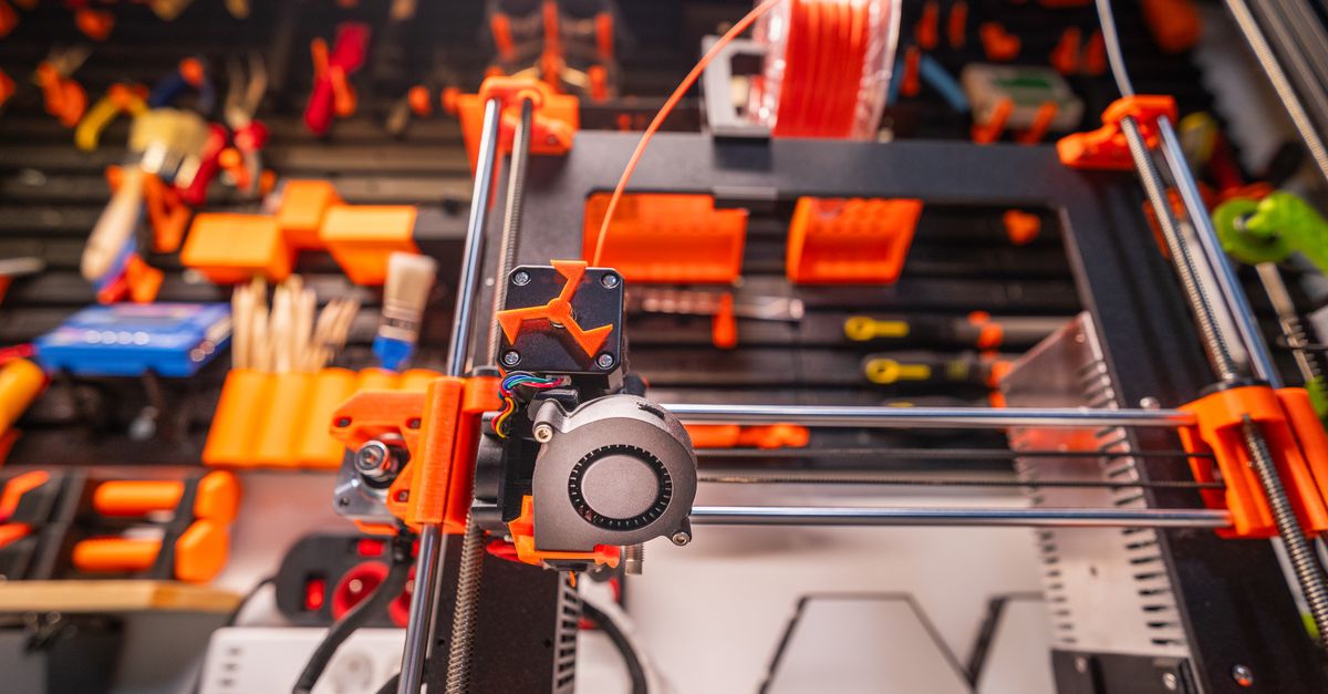
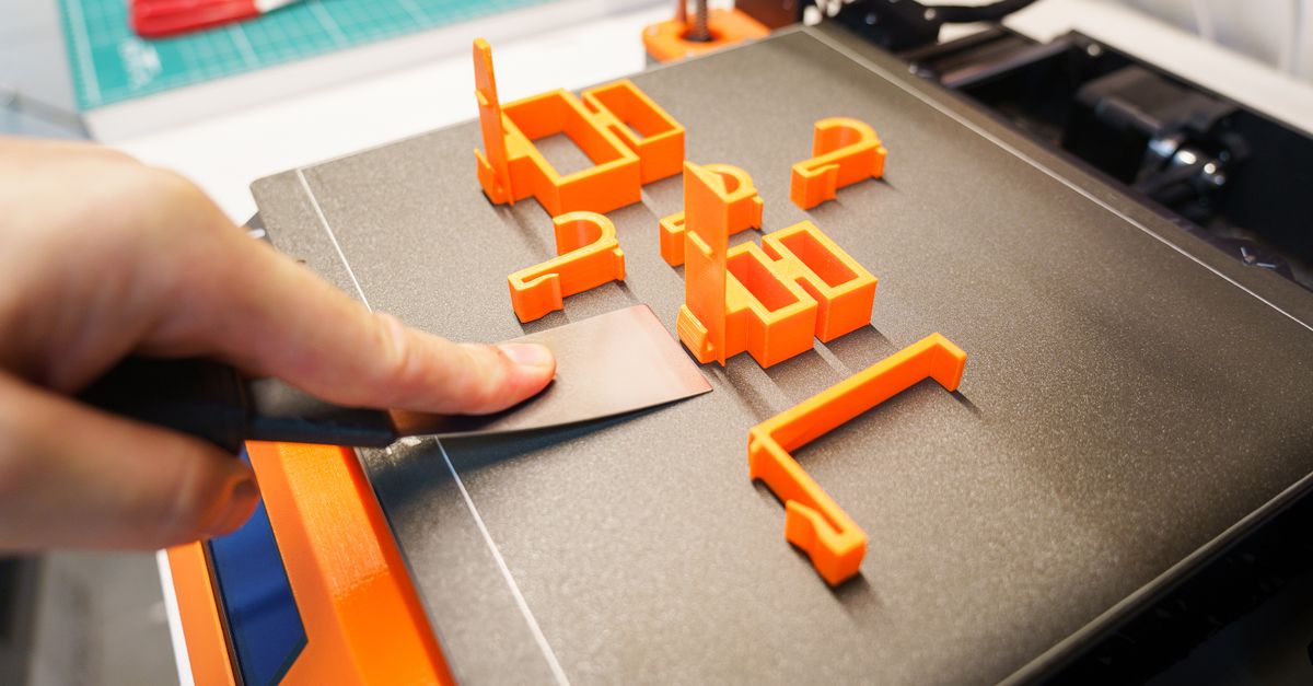
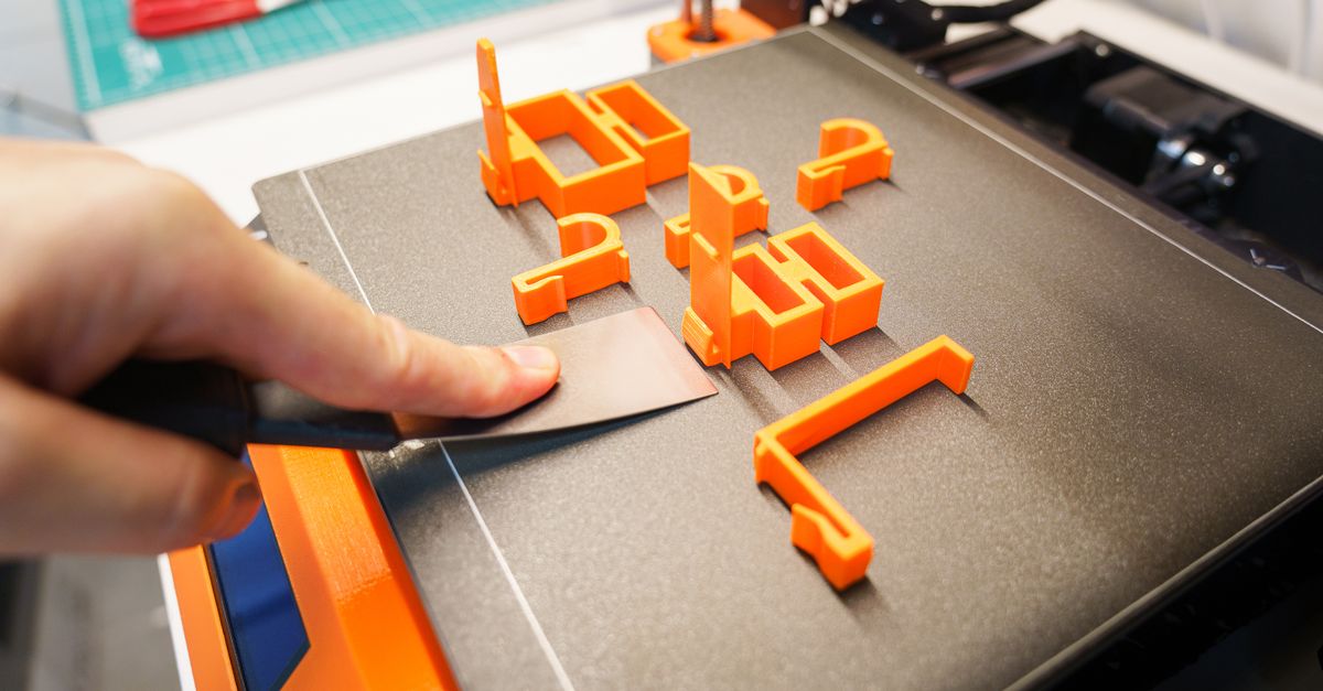
Every robot cell needs something between the robot flange and the part: grippers, fingers, suction cup mounts, sensor brackets. This is end-of-arm tooling (EOAT), and it is usually custom to the part being handled. Traditionally that meant machined aluminum with lead times measured in weeks. 3D printed end-of-arm tooling has become a practical alternative for a large share of these components, especially for light-to-moderate payloads and fast-changing product lines.
This post covers where FDM printing fits in EOAT, how to design printed fingers and mounts that hold up, which materials make sense, and where you should still reach for metal.
Why Print End-of-Arm Tooling at All?
Lead time is the biggest factor. When a new SKU arrives or a part design changes, the gripper often becomes the bottleneck. Machined tooling needs programming, setup, and shop queue time. A printed finger can go from CAD revision to physical part in a day or two, depending on size and print time. That changes how many gripper iterations you can afford during commissioning.
Weight matters more than most people expect. Every gram of EOAT subtracts from the robot’s rated payload and adds inertia at the end of the arm. Collaborative robots in particular often have payload ratings in the low single-digit to low double-digit kilograms, and the gripper, the part, and any sensors all count against that number. Printed parts with optimized infill and ribbed geometry are often substantially lighter than solid aluminum equivalents, which lets the robot move faster or handle heavier parts.
Geometry is free. Gripper fingers that conform to a curved part, hold a part by a contoured feature, or include built-in locating pockets cost about the same to print as a simple block. Machining those contours means extra setups or multi-axis work. For one-off and low-volume tooling, this is where printing wins on cost. If you want the broader economics, our post on the ROI of 3D-printed manufacturing tooling walks through the math.
Which EOAT Components Are Good Candidates?
Not every piece of a gripper assembly should be printed. In our experience with the technology, these are the strongest fits:
- Gripper fingers and jaw inserts. Custom-contoured fingers that bolt onto a standard pneumatic or electric gripper body are the most common printed EOAT component.
- Suction cup mounting plates and manifolds. Vacuum cup patterns can be matched exactly to a part’s flat or curved surfaces, with mounting bosses and cup positions built in.
- Sensor and camera brackets. Proximity sensors, vision cameras, and cable clips mount to printed brackets that can be adjusted and reprinted cheaply.
- Part nests and presentation fixtures. The fixtures that locate parts for pickup are close cousins of the jigs we cover in Fixtures and Jigs for Manufacturing Teams.
- Cable guides, covers, and guards. Low-load pieces where printing is almost always cheaper than any alternative.
The robot-side adapter plate and the gripper body itself usually remain metal. A common and sensible architecture is a standard aluminum flange adapter, a commercial gripper or vacuum generator, and printed custom interface pieces that touch the part.
How Should You Design Printed Gripper Fingers?
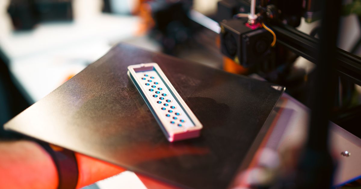
Photo by Jakub Zerdzicki on Pexels
Printed fingers fail for predictable reasons, and most of them are design problems rather than material problems. A few rules go a long way.
Orient layers so grip force does not peel them apart. FDM parts are weakest between layers. A finger that clamps a part will see bending load along its length, so the layer lines should not run perpendicular to the primary bending direction in a way that lets layers separate. In most cases that means printing the finger on its side or on edge instead of standing upright. Our guide on part orientation explains the reasoning in more detail.
Add walls before you add infill. For stiff, strong fingers, wall count and wall thickness contribute far more than infill percentage. A design with four to six perimeters and moderate infill, around 20 to 30 percent, is often stronger and lighter than a part with thin walls and dense infill. See Infill vs Walls: What Makes 3D Prints Strong for the full explanation.
Use fillets at every internal corner. Sharp internal corners concentrate stress and are where printed fingers typically crack first. A fillet radius of 2 to 3 mm at the base of a finger, where it meets the mounting surface, is a cheap fix.
Do not thread into plastic for repeated assembly. Fingers get swapped during changeovers, and bolts threaded directly into printed plastic strip out fast. Use heat-set inserts in the mounting holes so the interface holds up through many tool changes.
Design for the contact surface separately. The surface that touches your part may need grip, cushioning, or protection against scratches. Options include printed textured pads, bonded rubber or urethane pads, or a flexible TPU insert. We can print TPU, though it is not one of our daily-driver materials, so it is worth discussing before you commit to that approach.
Keep fits realistic. If a finger locates a part in a pocket, plan for FDM tolerances. We cover typical expectations in 3D Printing Tolerances: What to Expect, and for multi-part tooling assemblies the effects described in Tolerance Stackup in 3D Printed Assemblies apply directly.
What Materials Work for 3D Printed EOAT?
PETG is a strong default. It has good toughness, decent layer adhesion, and handles minor impacts better than PLA, which is more brittle. For fingers that see repeated clamping cycles and occasional crashes during commissioning, PETG is usually where we would start. It is also one of the two materials we print most often.
PLA is fine for prototypes and light duty. PLA is stiff, prints accurately, and is the cheapest option. It works well for first-iteration fingers, fit checks, and low-load brackets. Its main limitations are brittleness and a glass transition temperature around 55 to 60 C, so keep it away from hot cells, sunlit windows, or parked vehicles. Printed PLA under constant load can also slowly deform, which we discuss in Creep in 3D Printed Parts.
ABS, nylon, and carbon fiber composites are options for tougher jobs. We can print ABS periodically, and nylon and carbon fiber filled materials are within our capabilities, though they are not our everyday materials. Nylon offers better toughness and wear resistance. Carbon fiber filled grades add stiffness, which can matter for long, thin fingers. If your application needs one of these, talk to us early so we can confirm the right grade and print approach. Our PLA vs PETG vs ABS comparison is a good starting point for the basics.
Where Should You Not Use Printed EOAT?
Honest limits make for better tooling decisions. Printed plastic is not the right answer when:
- Loads are high or safety-critical. If a failed finger could drop a heavy part onto a person or equipment, use metal and follow your safety engineering process. Printed parts should not be the only retention method for anything hazardous.
- Temperatures are high. Handling hot parts straight from a process like molding or heat treating can exceed what PLA and PETG tolerate.
- Vacuum sealing is critical. FDM parts have microscopic gaps between layers and can leak. Printed vacuum manifolds can work with thick walls, careful settings, and sealing treatments, but expect to validate performance, and consider machined or purchased manifolds for demanding vacuum levels.
- Wear is severe. Abrasive parts or millions of cycles will wear plastic. Replaceable wear pads or metal inserts help, but at some volume, metal is the better economic choice.
- Chemical exposure is a concern. Coolants, solvents, and cleaning agents can attack some plastics. Check Chemical Resistance of 3D Printed Plastics before committing.
A reasonable approach is to treat printed tooling as the fast, flexible tier, and graduate to machined versions only for the components that prove they need it.
How Do You Iterate Quickly on Gripper Designs?
The real advantage of printed EOAT shows up when you plan for iteration instead of trying to get it perfect the first time.
Print a first-article set and test on the real part. Fit and grip behavior are much easier to judge in hand than in CAD. Rapid prototyping is a natural fit here: print, test, adjust, reprint.
Track revisions. Gripper finger revisions multiply fast. Label parts physically and keep CAD files organized, using practices like those in Version Control for 3D Print Files.
Keep spares. Because printed fingers are cheap, keeping a spare set on the shelf, or better yet the digital file ready for reprint, protects uptime. For multi-cell operations, our small-batch production service can supply matched sets so every cell runs identical tooling.
Think about changeover. If your line handles multiple part families, printed fingers make dedicated tooling per SKU affordable. That reduces the downtime and cost problems we outline in Tooling Changeover Costs Kill Profits.
What Should You Send for an EOAT Quote?
To quote printed gripper components accurately, we need:
- CAD files (STEP preferred) or the part geometry the gripper must handle
- The gripper body or mounting interface model, including bolt patterns
- Payload, cycle rate, and expected grip force
- Operating environment: temperature, chemicals, indoor or outdoor
- Quantity, including spares
If you do not have CAD for the fingers themselves, our custom design services can model them from your part and gripper specs. For the broader category of manufacturing aids, see our manufacturing tooling and fixtures page.
Talk to Us About Your Robot Cell
If you are commissioning a new robot cell, changing product lines, or tired of waiting weeks for gripper fingers, printed EOAT is worth a serious look. Send us your part and gripper details through our custom order page and we will tell you honestly whether FDM is a good fit, which material we recommend, and what a realistic design approach looks like. We serve the Charlotte metro area including the I-77 and I-85 corridors, and we ship nationwide.
Related Reading
Related Articles
Creep in 3D Printed Parts: Why Plastic Sags
Creep in 3D printed parts is slow deformation under constant load. Learn which materials resist it and how to design parts that keep their shape.
Reverse Engineering Broken Parts for 3D Printing
Reverse engineering parts for 3D printing turns a worn or obsolete component into a usable CAD model. Here is the workflow and the pitfalls to avoid.
Designing Snap Fits for FDM 3D Printing
Snap-fit design for FDM comes down to strain, orientation, and clearance. Here is how to build snap fits in PLA and PETG that do not crack.