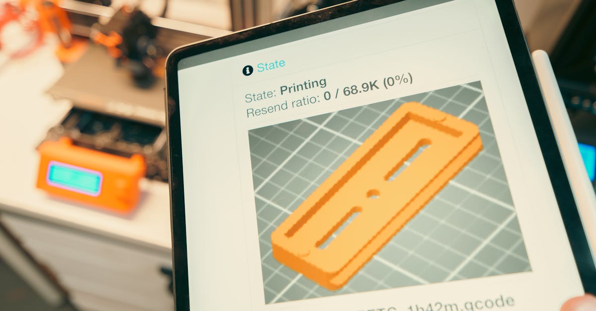
Photo by Jakub Zerdzicki on Pexels
Print Speed vs Quality: Finding Your Sweet Spot

Print Speed vs Quality: Finding Your Sweet Spot
The eternal question in 3D printing: how fast can you go without sacrificing quality? Every business faces this trade-off when ordering 3D printed parts. Understanding the relationship between print speed and quality helps you make informed decisions that balance your timeline, budget, and performance requirements.
At CLT 3D Printing, we navigate this balance daily with our FDM printers. The sweet spot varies dramatically depending on your application - what works for a quick concept model might fail spectacularly for a functional prototype that needs to withstand testing.
Understanding Layer Height Impact
Layer height drives both speed and surface finish. Thicker layers print faster but create visible stepping on curved surfaces. Thinner layers take longer but produce smoother results. Consider these typical scenarios:
For rapid concept models, 0.3mm layers can cut print time by 50% compared to 0.2mm layers. The visible layer lines might actually help stakeholders understand that they’re looking at a prototype, not the final product. This psychological distinction can facilitate more open feedback during design reviews.
Functional prototypes often require 0.2mm or finer layers, especially for parts with mating surfaces or aesthetic requirements. The extra time investment pays off in parts that accurately represent your final design intent. We regularly print PETG prototypes at 0.15mm for automotive clients who need parts that both look and perform like production components.
Speed Settings Beyond Layer Height
Print speed involves more than just how fast the print head moves. Modern slicers control dozens of speed parameters independently:
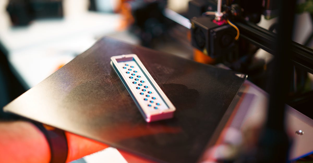
Photo by Jakub Zerdzicki on Pexels
Perimeter speeds affect dimensional accuracy. Slower outer wall speeds (typically 30-50mm/s) produce cleaner surfaces and tighter tolerances. Inner walls can run faster since they’re hidden. This differentiation lets you optimize for both speed and appearance.
Infill speeds can push limits safely. Since infill is internal, you can often double or triple the speed compared to perimeters. Running infill at 80-120mm/s while keeping perimeters at 40mm/s maintains quality where it counts while reducing overall print time.
First layer speed determines adhesion success. Starting too fast risks print failure. Most successful prints begin at 15-25mm/s for the first layer, ensuring proper bed adhesion before accelerating.
Material-Specific Speed Considerations
Different materials have unique speed limitations based on their thermal properties:
PLA: The Speed Champion
PLA’s low melting temperature and minimal shrinkage make it the fastest-printing material in our arsenal. We routinely run PLA at 60-80mm/s for general features with excellent results. The material’s forgiving nature means you can push speeds higher for draft prints - sometimes exceeding 100mm/s for rough prototypes.
PETG: The Balanced Performer
PETG requires more finesse. Its higher printing temperature and tendency to string means optimal speeds typically range from 40-60mm/s. Pushing faster often creates surface defects or dimensional issues. The trade-off? PETG’s superior strength and chemical resistance justify the extra time for many applications.
ABS: The Temperamental Speedster
ABS can match PLA’s print speeds but demands perfect environmental control. Without a heated chamber, fast printing amplifies warping and layer adhesion issues. When conditions are right, ABS prints beautifully at 60-70mm/s. When they’re not, even 30mm/s can produce failures.
Real Performance Trade-offs
Mechanical strength varies with print speed. Faster printing can reduce layer adhesion, especially with materials like PETG that benefit from slower, hotter extrusion. A part printed at 80mm/s might have 20-30% lower tensile strength than one printed at 40mm/s, depending on the material and geometry.
Dimensional accuracy suffers at extreme speeds. Acceleration and deceleration create forces that can cause ringing, ghosting, and dimensional variations. Critical tolerances often require slower speeds to maintain precision. For press-fit assemblies or parts requiring post-processing, the time saved printing fast can be lost to additional finishing work.
Surface quality degrades predictably. Higher speeds amplify every imperfection - from inconsistent extrusion to mechanical vibrations. Visible surfaces benefit dramatically from reduced speeds, while hidden internal features can run at maximum speed without consequence.
Optimizing for Your Timeline
Smart speed optimization considers the entire project timeline, not just print time:
Design iteration cycles benefit from speed. During early prototyping, fast draft prints accelerate learning. A 4-hour print at 0.3mm layers beats waiting 12 hours for a perfect 0.1mm version when you’re still refining the design. We often recommend starting fast and refining quality as designs mature.
Production runs require consistency. Small batch production of 10-50 units demands repeatable quality over raw speed. Slightly slower, more conservative settings reduce failure rates and rework time. A 20% speed reduction that eliminates one failed print per batch actually saves time overall.
Deadline pressures need honest assessment. Pushing speed to meet tight deadlines risks quality issues that could delay delivery even more. Better to have an honest conversation about realistic timelines than to deliver parts that don’t meet specifications.
Advanced Speed Optimization Techniques
Modern slicing software enables sophisticated speed control:
Adaptive layer height saves time intelligently. This feature automatically uses thicker layers for simple geometry and thinner layers for detailed areas. A part might print with 0.3mm layers for the base and 0.1mm layers for fine features, optimizing both speed and quality where each matters most.
Variable line width reduces print moves. Allowing the slicer to vary extrusion width slightly can eliminate thin gap-fill moves that add time without improving strength. This optimization can reduce print time by 10-20% with minimal quality impact.
Support interface layers enable hybrid approaches. Printing support structures at high speed with rough quality while using fine settings for support interfaces maintains part quality while reducing overall time.
Making the Right Choice
Define “good enough” for your application. A manufacturing jig might need dimensional accuracy but not aesthetics. A customer-facing prototype might need smooth surfaces but not full strength. Understanding your actual requirements prevents over-specifying quality at the expense of time.
Consider post-processing in your timeline. Sometimes a fast print followed by light sanding beats a slow, perfect print. Other times, the opposite is true. Factor finishing time into your speed decisions.
Test critical features first. For complex parts, consider printing just the critical features as a test piece. This validates your speed/quality balance before committing to a full print.
Speed Guidelines by Application
For rapid prototyping, prioritize iteration speed. Use 0.2-0.3mm layers, 60-80mm/s print speeds, and 20-30% infill. These settings work well for form studies, fit checks, and design validation where surface finish is secondary to getting parts quickly.
For functional testing, balance durability with timeline. Use 0.15-0.2mm layers, 40-60mm/s speeds, and 40-60% infill with appropriate wall thickness. Parts need enough strength for testing while maintaining reasonable print times.
For presentation models, quality trumps speed. Use 0.1-0.15mm layers, 30-50mm/s speeds, and optimize for surface finish. The extra time investment pays off in parts that accurately represent your vision to stakeholders or customers.
For production parts, consistency is king. Use conservative settings that produce reliable results across batches. Small variations in speed between batches can create fit issues in assemblies.
Finding Your Balance
The optimal speed/quality balance is unique to each project. What works for a one-off prototype might fail for a production run. What’s acceptable for internal testing might disappoint a customer.
We guide clients through these decisions daily, helping match print settings to actual requirements. Sometimes that means pushing speeds to meet urgent deadlines. Other times it means slowing down to ensure critical tolerances. The key is understanding your options and making informed choices.
Speed and quality exist on a spectrum, not as binary choices. Modern 3D printing technology offers incredible control over this balance - the challenge is knowing how to use it effectively for your specific needs.
Ready to Optimize Your 3D Printing Project?
Whether you need parts fast, need them perfect, or need the optimal balance between the two, we’re here to help. Our experience with materials, geometries, and applications helps us recommend the right approach for your timeline and requirements. Start your custom order today and let’s find your sweet spot.
Related Resources
Related Articles
Waterproofing 3D Prints: Methods & Materials
Learn proven techniques to make FDM 3D printed parts waterproof for outdoor and liquid-contact applications.

3D Printing Validation Testing Guide
Master validation testing for 3D printed parts with dimensional checks, strength tests, and material verification methods.

Cost-Per-Part Calculator for 3D Printing
Master the hidden variables that determine your true 3D printing costs and make smarter sourcing decisions.